TG3000 & TG6000 TRACKING GENERATOR’s & SIGNAL GENERATORS
Theory and Operation
© DS Instruments
Oct 2013
for a pdf version of this article ->TG_ARTICLE_DSI_v3
Using a Spectrum Analyzer (SA) in combination with a Tracking Generator (TG) enables swept scalar frequency response measurements of active and passive networks. Many commercially available RF spectrum analyzers provide this function, usually as a built in option. DS Instruments has designed two generic, self-contained, TG instruments that reside external to the host SA; the TG3000 and TG6000. The TG3000/TG6000 can replace the HP 85640A . These TG’s provide not only a classic TG signal but can also be used as a wide band Signal Generator. In addition the typical factory installed TG’s often only provide a signal for the first band of the SA. For those SA’s that have higher bands the TG6000 will produce a TG signal that will cover the first high band. Additionally a method is shown that allows the TG3000/6000 to sweep DUT’s that have internal frequency conversion.
A Single Swept LO allows Simple TG Implementation
It is possible, with many SA’s, to easily construct a TG with just a few RF building blocks. Figure 1 shows common type of RF spectrum analyzer architecture with the TG function implemented using a mixer, amplifier and a Signal Generator (SG) set to a fixed frequency (1st IF). The device to be swept, the DUT in figure 1, is connected between the TG and the host SA as shown. The technique of TG generation presented here will only work with spectrum analyzers that sweep only the 1st LO to achieve its frequency scan. That particular technique is found in many Agilent/HP instruments. Many SA’s sweep another LO in addition to the first LO. Such instruments are not suitable for TG generation using the method described here. In addition to the condition that all SA sweep is done by the 1st LO, the SA must have a sample output of the 1st LO available. Lastly RBW filters need to be the “fixed” in frequency type and not of the FFT type, which is actually a bank of filters.
Figure 1: Typical SA Architecture
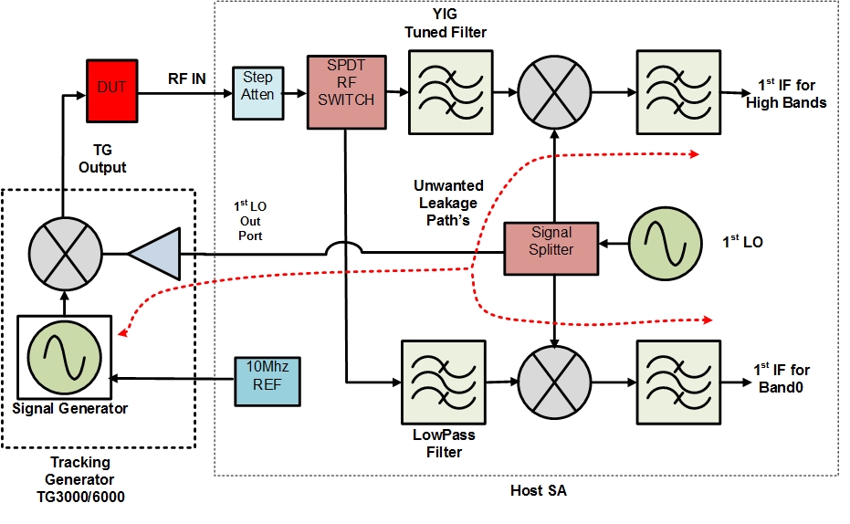
A simple Mix of the SG signal with SA 1st LO produces TG signal
When the 1st LO is mixed with the TG’s internal Signal Generator output, with its frequency @1st IF, the output of the mixer will contain a frequency component that is exactly the RF signal the analyzer is tuned to at that point in its sweep. This signal is the TG signal. The DUT is placed between the mixer output and the RF input of the analyzer. As long as the band of the Spectrum analyzer is not changed further adjustment of the frequency of the Signal Generator is not needed. The TG output now will automatically track via the swept 1st LO, thus providing a perfectly synchronized signal for swept scalar measurements.
TG internal Signal Generator is Phase Locked
The internal SG of the TG3000/6000 is phase locked to the host Spectrum Analyzers 10MHz reference. This insures that during use the TG output signal will remain stable and at the exact frequency needed by the host SA. This is particularly important if a narrow RBW is used in the SA during TG sweep operation. Without locking the TG internal source to the SA 10MHz reference the TG signal could drift off and out of the RBW being used. When just the SG output of the TG3000/6000 is to be used the phase locked synthesizer will a produce stable high quality RF signal.
Isolation Issues
It’s tempting to connect the LO output of the Spectrum analyzer directly to the mixer used to generate the TG signal. With most spectrum analyzer’s this will cause a problem. There is usually not enough isolation in the reverse direction of the 1st LO out port of the SA. The result is the TG’s Signal Generator is sitting at the 1st IF frequency and this can leak back into the SA and get into the 1st IF. This will flood the first and subsequent IF’s of the analyzer. The result is a raised noise floor and reduction in dynamic range. This unwanted path is shown figure 1.
A circulator could be used to increase isolation. A single Circulator will provide about 20dB of isolation and reduce 1st LO power to the mixer. For the TG3000/6000 a high isolation amplifier was designed that provides over 50dB of isolation up to approximately 6GHz. In addition it allows broadband operation and good LO drive level when a low 1st LO level is all that available. The high isolation amplifier is designed to work with 0dBm as input power level.

Figure 2: The TG3000 Figure 3: The TG6000
TG3000 and TG6000, Self-Contained Generic TG’s
The TG3000 and TG6000 are both are based on the approach shown in figure 1. In the TG3000 and TG6000 the mixer, high isolation amplifier and a wide band Signal Generator are integrated into a single instrument as shown in figure 2 and 3. In the TG6000 the RF/IF mixer ports are brought to the front panel so that Band0 and Band1 operation is supported. The TG3000 is setup just for Band 0 operation. The TG3000 will cover a Band0 range from 100 KHz to 3GHZ. The TG6000 will cover from 100 KHz to 6GHz in two bands, 0 and 1. The internal signal generator is brought to the front panel of both instruments. This allows this the TG3000/6000 to also function as standalone wide band signal sources. For supported SA’s no PC connection to a host computer is needed to use either the TG3000 or the TG6000 as TG source.
Using the TG3000 with the HP8566A/B to sweep Band0
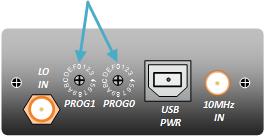
Figure 4 shows the test setup for the TG3000 system with the HP 8566A/B Spectrum Analyzer so as to cover the instruments first band which extends from near DC to 2.5GHZ. The TG3000/6000 are power from USB port on rear of the instrument. This can be from a computers USB port or a wall adapter that provides a powered USB jack. Before using the TG the user selects the host SA being used by setting the two rotary switches on the rear panel of the TG3000, see figure 6. These switches configure the TG3000 for the particular instrument being used. For the HP 8566A/B the 1st IF in band0 is 3621.4 MHz. The internal SG of the TG3000 will be automatically set to this frequency by the rear panel switches. For supported SA’s no PC connection is needed to configure the TG3000/6000 for TG use. The 3dB pad on the I-port improves the VSWR that the DUT sees looking back towards the TG3000. The 6dB pad on LO signal from the 8566 improves the isolation to that port. The TG3000 and TG6000 are optimized for a 1st LO level of approximately 0dBm at the rear panel input.
Figure 4: TG3000 Setup with HP8566A/B Band0
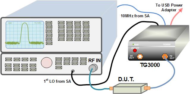
Figure 5: Rear Panel SA Select Switches
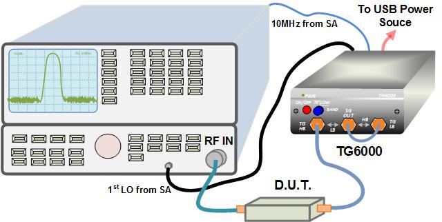
Using the TG6000 with the HP8566A/B to sweepBand1
Figure 6 shows the TG6000 setup for creating the TG signal for the 1st high band of the HP8566. As with the TG3000 the user selects the HP8566A/B configuration using the rear panel switches, see figure 5. The front panel high/low band select switch is set for HIGH band operation. For high band operation the signal generator output port (the middle SMA on the TG6000) is connected to the TG LB port as shown in figure 6. The first IF of the HP8566 for all its high bands (2 to 22GHZ) is 321.4MHz therefore the signal generator is set to 321.4MHz. The R-port of the mixer now contains the desired TG signal and its unwanted image. The YIG tracking filter on the input of the HP8566A/B will virtually eliminate the unwanted frequency products. The user should be aware of the unwanted product, as both unwanted and desired products will be presented to the DUT input.
Figure 6: TG6000 High-Band (Band1) Setup HP8566A/B
Disable the auto Frequency Shift in BAND0
Some SA’s may use two settings of their 2nd LO when sweeping Band0 . The reason (tpically) is to dodge low level spurious mixer products as the SA sweeps. This shift is known to be used by the HP8568A/B. It can be disabled in the HP8568B using the command sequence “SHIFT T”. If this is not done the TG signal will not be at the correct frequency in those locations where the HP8568 steps its 2nd LO. No degradation will occur in TG performance with shift disabled. The shift should be re-enabled for normal SA operation.
Non Supported SA’s, Determining the correct SG frequency
If DS Instruments does not support your SA you can use the following procedure to find the correct internal SG signal for TG operation. Of course if your SA sweeps another LO in addition to the 1st LO then you cannot use the TG3000/6000, see above. Referring to figure 1, the TG’s internal SG signal generator is set to the 1st IF frequency of the band in use. The frequency of the 1st IF can be found from manufacture’s data or by experimentation. By careful injection of the TG 3000/6000 SG (or any SG) signal directly at the RF input of the spectrum analyzer, observe when the IF starts to “flood” the instrument (as indicated by a rising noise floor). You will need to command different SG frequencies using a PC with supplied SW and USB cable. Initially use set the host SA to its widest RBW to coarsely find the 1st IF frequency. When you see the noise floor move you are near the 1st IF frequency of the SA. You can refine your estimate of the exact 1st IF frequency by using narrower and narrower RBW’s and tuning the SG for “peak” amplitude of the elevated noise floor.
Video Leveling and Dynamic Range of TG3000 with HP8566A/B
Using the video memory of the HP8566A/B it is possible to correct the response of the TG3000 or TG6000. If a thru device is connected as the DUT in figure 4 the swept response will be similar to that shown in Photo 1. When the DUT is a short section of transmission line the ideal response should be a flat line. Instead we see the system response which is pretty flat.
We can use the video memory and arithmetic features of the HP8566A/B to correct for the non-flat response seen in Photo 1. Once we set this up the correction will be applied in real time for each sweep. As long as the frequency axis settings are not changed the correction will remain valid.
The first step is turn on the DISPLAY line and position it near the swept response of the thru DUT. Now using video subtraction store the difference between the display line and the swept response in VIDEO A into VIDEO B memory. Now Perform A-B video subtraction and the A sweep is now a flat line. The imperfections of the system have been reduced using this method. The analyzer is subtracting out (in video) the roll in the “thru” response. The result of the video subtraction is that a “thru” connection results in a ~flat trace.
Photo 2 also shows the noise floor when the DUT is replaced with 50Ω terminations on the TG and SA ports. Because the level correction is done using video memories (VIDMEM_A- (VIDMEM_B-DL)) the noise floor rises at the high end due to the roll off in photo 2 . Thus photo 2 also shows the achievable dynamic range with TG3000/HP8566A/B to be approximately 80dB using a 10KHz RBW.
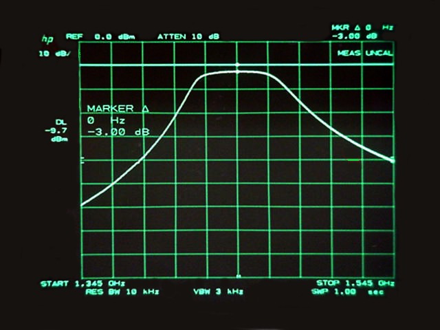
An Example: Sweeping a Bandpass Filter
In photo 3 the TG3000 was used to measure the frequency response of a BPF filter with a center frequency of 1445MHz. The start frequency is 1345MHz and the stop frequency is 1545MHz. The display vertical is 10dB/div, internal attenuation 10dB, sweep time 1 second, RBW 10Khz and VBW is 3KHz. Before the trace was taken the reference line was set by using video subtraction as discussed above to remove the variation in TG output level. The dynamic range exceeds 80dB for this sweep.
Photo 1: Uncorrected Band0 response of a THRU type DUT, TG3000 and HP 8566A/B SA
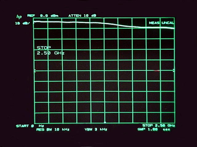
Photo 2: Corrected THRU sweep using video memory and noise floor after correction.

Photo 3: Sweep of a BPF at CF 1445 MHz using TG3000 and HP8566A/B SA
Using the TG3000/6000 to Sweep Frequency Converters
Many existing TG’s for SA’s do not allow the user to “offset” the input signal so as to sweep DUT’s such as a mixer or a frequency up/down converter. With the TG3000/6000 it is possible to do such sweeps as long as the frequency offsets introduced by the DUT do not exceed limits imposed by the SA 1st IF frequency. By entering an offset at the SG internal to the TG3000/6000 systems, frequency active DUT’s can be swept as a complete system. Such system sweeps are the combined effects of many individual elements such as filters, amplifiers, mixers, etc.
Figure 7 shows an example setup for using the TG3000 module in combination with the HP8566 to sweep a frequency down converter as the DUT. The example DUT applies its input to a SAW BPF @ 254MHz, BW~5MHZ. After amplification the DUT then converts the 254MHz signal to 21.4Mhz. The conversion is done using a LO frequency of 232.6Mhz provided by the DUT. The DUT then applies the 21.4Mhz to a BPF @ 21.4MHz, BW~2Mhz. The overall frequency response of this DUT will be determined by the combined responses of the BPF@ 254MHz, [email protected].
Normally to use the TG3000 with the HP8566A/B in band0 the internal SG would be set to 3621.4MHz. But since the DUT of our example has a mixer with a LO at 232.6MHz we must compensate for this, otherwise our TG3000 output signal will be incorrect. The solution is to offset the internal SG by –232.6Mhz, which will result in an SG frequency of 3388.8MHz. This puts the TG output at the correct frequency for this DUT’s particular internal frequency offset. To program the internal SG of the TG3000 for this new frequency requires that a PC be connected via the USB port. Use the supplied SW to set the frequency of the TG3000 internal SG to 3388.8MHz.
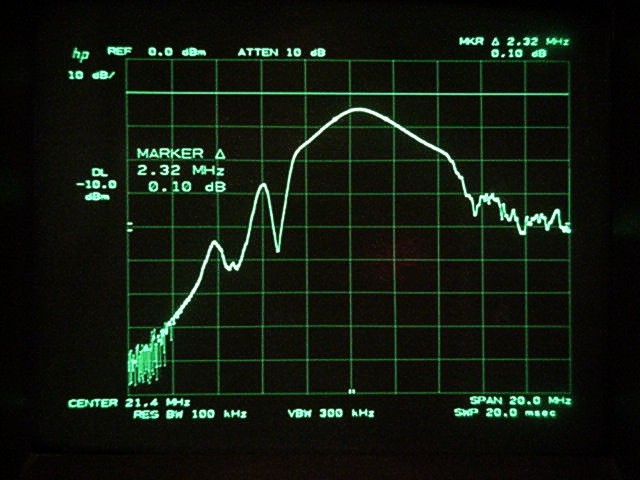
Photo’s 4&5 shows the frequency response of the 254MHz SAW BPF and 21.4Mhz BPF respectively. These were measured individually using the TG3000/HP8566 as described above for passive devices. Photo 6 shows the complete down-converter response using the TG3000 with the SG offset as described above. The combined response shows how the skirts of the filter @ 254MHz add to those of the @21.4MHz in a wide band sense.
Figure 7: Down-converter DUT being swept by TG3000/HP8566A/B
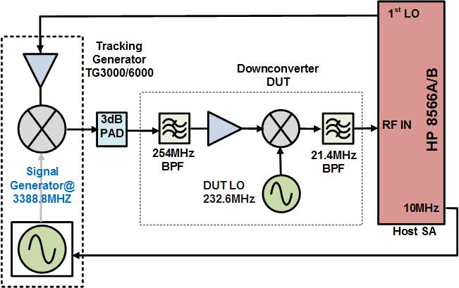
Photo 4: 21.4MHz Band-pass filter response using TG3000/HP 8566A/B Band0,SPAN=20Mhz
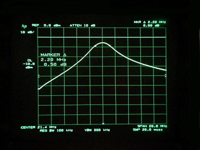
Photo 5: 254MHz Band-pass filter response using TG3000/HP 8566A/B Band0,SPAN=20MHz
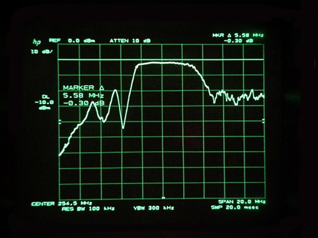
Photo6: Combined response of the 254MHz and 21.4 MHz BPF 21.4MHz, swept
using TG3000/HP 8566A/B Band0 with OFFSET applied to SG, see text. SPAN=20MHZ
- TRACKING GENERATOR FOR HP 8566A/B
- TRACKING GENERATOR FOR HP 8568A/B
- TRACKING GENERATOR FOR HP 8569A/B
- TRACKING GENERATOR FOR HP 8560 all versions
- TRACKING GENERATOR FOR HP 8561 all versions
- TRACKING GENERATOR FOR HP 8562 all versions
- TRACKING GENERATOR FOR HP 8563 all versions
- TRACKING GENERATOR FOR HP 8564 all versions
- TRACKING GENERATOR FOR HP 8590 all versions
- TRACKING GENERATOR FOR HP 8591 all versions
- TRACKING GENERATOR FOR HP 8592 all versions
- TRACKING GENERATOR FOR HP 8593 all versions
- TRACKING GENERATOR FOR HP 8594 all versions
- TRACKING GENERATOR FOR HP 8595 all versions
- TRACKING GENERATOR FOR HP 8596 all versions