Using a Dual Channel Power Meter in Differential mode to make high precision Path Loss Measurements
DSI Staff, 2014
Description of Method
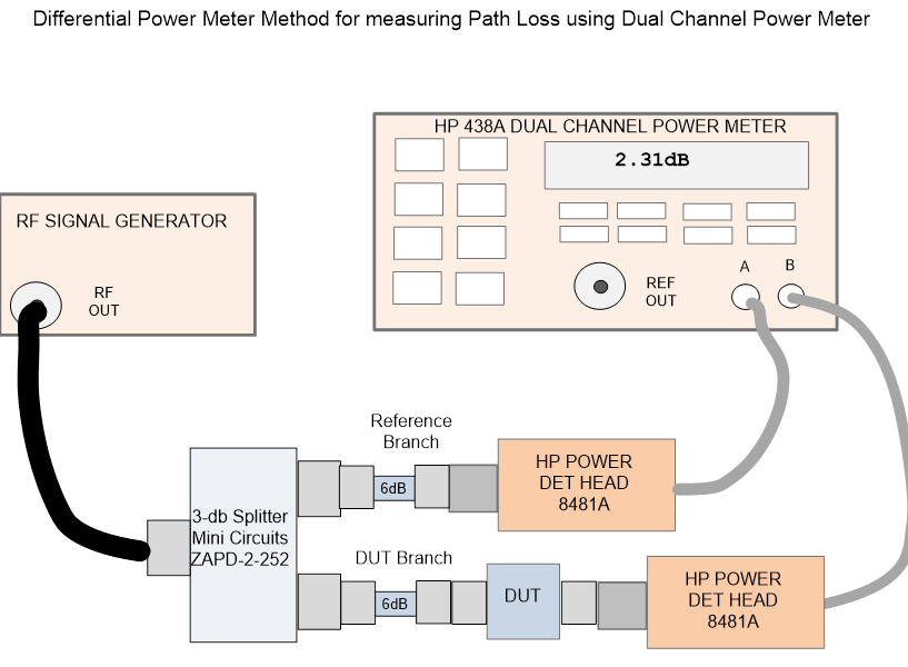
Figure 1 shows the basic connection of HP 438 dual channel Power meter, signal source, signal splitter and DUT. The branch connected to Channel A of the power meter is the Reference Power path. This method is a delta measurement method and as such produces a dB value not a dBm value on the meter display during measurement. The branch connected to Channel B of the power meter is the DUT branch. The RF signal source is to the frequency of interest and its power level to approx. +10dBm. The splitter as shown is a 3dB type but could also be a directional coupler. The 6dB pads improve the isolation of the 3dB splitter w.r.t. DUT VSWR and are optional for low VSWR splitters and DUT’s. In the case of a directional coupler more resistance to thru port VSWR/Isolation issues of the DUT is inherent. The meter and the two heads used should be zero and calibrated using the meter reference signal and built in meter functions, see operation manual for the meter used. The meter, and heads, should be allowed to warm up for about an hour prior to this self-cal. If small absolute bias are left on the either or both the power heads after calibration it should not matter. The final accuracy of this delta method depends not on the power head absolute accuracy but rather the linearity of the detector heads used.
Before the DUT is inserted into the splitter network the two power heads are connect to the two splitter ports. The meter is set to take the difference (in dB) of the two power heads or A-B. The difference displayed on the meter with no DUT is a measurement of zero loss or baseline path loss. That value is then entered into the power as an OFFSET value which is then automatically subtracted from the power difference as displayed on the meter. Once this is done the meter will display very close to zero dB as the difference between channel A and channel B is now calibrated. Once meter is calibrated and OFFSET from above is entered, the DUT is inserted. Now the power meter will DIRECTLY read out the loss/attenuation of just the DUT. This OFFSET value is only valid at or near the frequency of interest. If frequency is changed significantly a new OFFSET must be measured.
This Method is largely immune to variations in SG power level and produces relative data, not absolute power level data
When doing a single head loss measurement it is necessary to record an absolute power level into the DUT, from the SG ( typically in dBm) , then later measure the absolute power level out of the DUT , then subtract the two levels to arrive at DUT loss. During the time it takes to move the head the SG level can change introducing error in loss measurement or perhaps cable loss ( to the splitter) might change due to bending. In the dual head differential method the reference applied power is measured nearly simultaneously as the output DUT power with the subtraction of two powers done automatically in the meter itself. This near simultaneous measurement of applied power and DUT output power makes the differential method nearly immune to fluctuations of SG power level as seen at the input of the splitter. The differential (delta) method never needs a separate recording of absolute level for later subtraction, all the data produced is relative and typically in expressed in dB. The cable loss from the SG to input port of the splitter is typically of no concern as long as it remains relatively stable over the short differential measurement time used by the meter. The power meter can be configured to average longer and more readings as each measurement is using the SG power only during that measurement instant, the next measurement could us a different signal power but produce the same delta, thus longer averaging is possible with delta method. Longer averaging means less noise in the reported delta measurement.
Maximum Loss capability of method
The maximum loss measureable by this method is determined by the range of the power heads used and the power level of the SG. For the case where two 8481A power heads are used and a SG reference power level of 10dBm is used, the maxim loss the system is able to measure is about 30dB. If more range is needed use a more sensitive head on the DUT branch and a higher power head on the reference branch of the power splitter.
In such a case the signal generator power may have to be lowered when measuring the OFFSET scale value and raised when measuring the DUT. This insures both branches are operating at appropriate power levels during OFFSET measurement and DUT measurement. If the 8481D head is used in the DUT branch and the 8481A head in the Reference branch, then it is possible to directly measure losses in excess of 60dB with high accuracy. In this case the OFFSET value of the splitter could be measured with SG power near -20dBm , which should still be acceptable to the high power head and the low power head. The 8481D has a stated range of -20 to -70dBm while the 8481A has stated range of -30 to +20dBm. If at all possible keep power ~5dB away from stated absolute power limits of the heads used. This should minimize measurement uncertainty.
Once the measurement is setup the SG power should be changed slightly to verify the delta measurement remains unchanged as SG power is changed. The range of the SG level movement should be such that the absolute power at DUT branch and Reference branch remains within limits of the heads used.
Uncertainty of Loss measurement
The final uncertainty of the measurement will be largely dependent on the uncertainty of the power heads used. Not all power heads and meters are suitable for high accuracy measurements. The uncertainties of the heads and their respective meter should be investigated before using the differential method in high accuracy measurements. Agilent/Keysight has uncertainty computation tools for their line of power meters and heads. These tools allow the user to enter power level and frequency. A total measurement uncertainty is then computed for those specific measurement parameters. The uncertainty of the measurements made using the setup and equipment shown in figure A1 is estimated to be better than +/-0.2 dB for DUT losses less than ~30dB.
Reduced Uncertainty of delta power measurement due to subtraction of common error terms
By using the dual head or delta approach with the same model of power head on each channel the resultant displayed difference should have lower uncertainty than a single head measurement. The reason is that many of the error terms in the two separate power measurements for channel A and B are common in each channel and therefore subtract away. The reduction of measurement uncertainty combined with reduction in SG power level sensitivity can make the differential power loss measurement very accurate when executed properly.
Even in the case where different model number or types of heads are used for the DUT and reference branch uncertainty should be reduced as some of measurement uncertainty is due to meter body functions, which is still common to both heads.